



 EN
·
EN
·  DE
DE3D Ring-Core Shaper
An all-reflective ring or ring-and-core profile that holds steady across the full depth of focus: a calmer process zone, less spatter and repeatable results in welding, cutting and additive manufacturing. One passive optic delivers the ring-core beam of a dual-mode laser at a fraction of the cost, built for volume production.
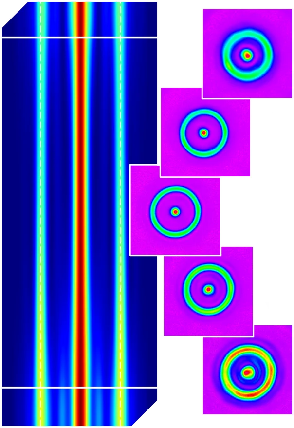
A stable process zone that holds through the depth of focus
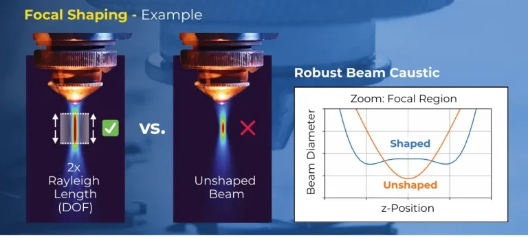
In welding, cutting and additive manufacturing, a plain Gaussian beam often can’t hold the process steady. Focus drift and thermal lensing shift its size and intensity right at the workpiece: the keyhole or melt pool turns unstable, spatter increases, and the result drifts. The Ring-Core Shaper wraps the central spot in a ring and holds both steady across the full depth of focus. That keeps the process zone calm, lets feed rates run faster without fouling, and holds quality even in multi-kW setups. One passive optic delivers that ring-core beam without an expensive dual-mode laser, which is what keeps it economical for series production.
Built for reliable volume production
Unmatched depth-of-focus
Up to 5× the propagation stability of a typical dual-mode (fiber) ring-core laser, whose ring structure collapses within a fraction of the Rayleigh length.1 The ring and core keep their shape well beyond the focal plane: a wider, more forgiving process window.
Exceptional homogeneity
A clean, uniform ring with the smallest possible core: the energy lands where you want it, for consistent seams and edges.
Resistant to thermal lensing
All-reflective, micro-structured mirror optics hold steady at power, which makes them ideal for multi-kW setups where transmissive optics drift.
We individualize ring diameter and the power ratio between ring and core to your specification and system as standard.
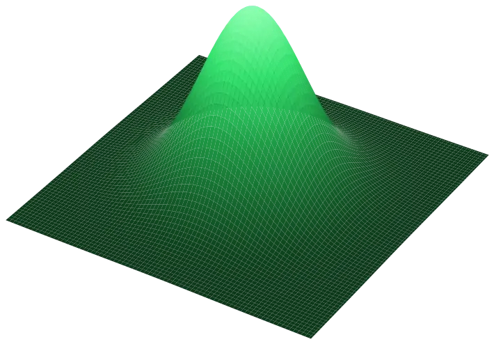
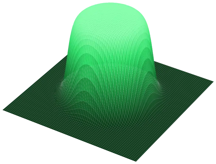
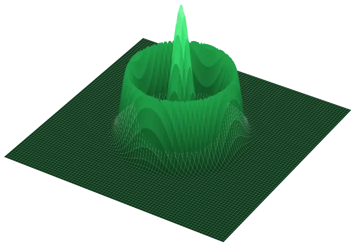
From a bright ring to a strong core: your power ratio
The split of power between the ring and the central spot is a design choice: we set it to your process, anywhere from a dominant ring to a dominant core, and the ring you choose extends the effective spot size.
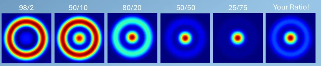
Ring/core power ratio, shown 98/2 → 25/75 and fully custom. Typical efficiency 77% (pure ring) to 89% (50/50 ring-spot). Exact profile confirmed per configuration.
Propagation-stable ring-core: verified at the focal plane
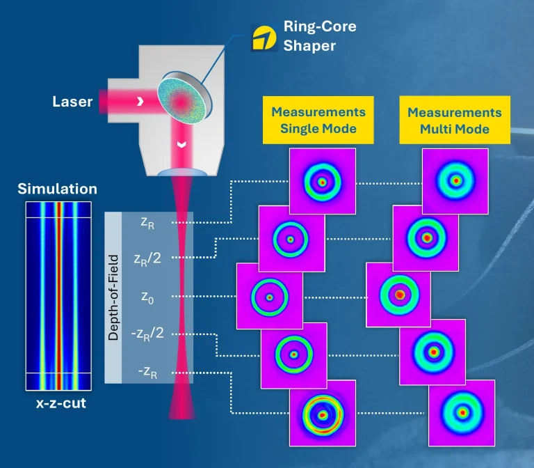
Measured at the PRIMES Application Lab with a Primes MicroSpotMonitor MSM+, on single- and multi-mode systems up to 3 kW. The measurements agree closely with design and theory.
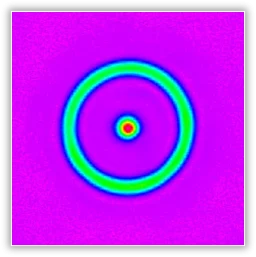
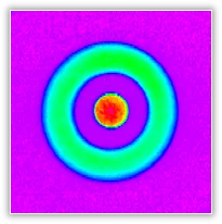
Conditions: These values apply to the configurations above and depend on wavelength, input beam, M², optical layout and application. We confirm the numbers for your exact setup instead of relying on catalogue estimates.
The profile stays intact across the entire depth-of-field
Simulation and measurement agree: the ring-core profile holds its shape from −zR through focus to +zR. That propagation stability keeps the keyhole calm and the process resistant to thermal lensing. That’s the whole point of ring-core for volume production.
- Stable propagation over the entire depth-of-field
- Highest homogeneity with the smallest feature size
- Customized ring diameters & power ratios
Will it fit your setup?
Every Ring-Core Shaper is matched to your laser and process. We design against the parameters below: send them and we confirm fit for your exact configuration.
Recommended setup: integrate into a collimated beam with a focusing lens. For setups without a lens, contact us for analysis.
Specifications
| Parameter | Characteristic |
|---|---|
| Ring-core geometry | |
| Core width | 1.0 × Gaussian spot diameter (1/e²) |
| Ring width | 0.8 × Gaussian spot diameter (1/e²) |
| Ring diameter | Individualized |
| Efficiency | 85–95% | >95% version available on request |
| Depth of focus | ~100% of Gaussian spot for both core & ring |
| Input beam requirements | |
| Input beam | Works with single- or multi-mode |
| Input beam diameter | Up to diameter 16 mm (AOI = 45°) |
| Wavelengths | 1064/1030 nm; 532/515 nm; 450 nm; 355/343 nm; 266 nm; others on request |
| Clear aperture | ≥ 2× beam diameter (1/e²) |
| Integration | |
| Alignment | Lateral alignment required |
| Setup | Recommended: integrate into a collimated beam with a focusing lens. For setups without a lens, contact us for analysis. |
| Further specs | |
| Material | Micro-structured dielectric HR coating on fused silica substrate |
| Reflectivity | >99.9% @ 1064/1032 nm; 532/515 nm; 355/343 nm — >99.8% @ 266 nm |
| Dimensions | Ø25 mm/1″ and Ø50 mm/2″. Other dimensions on request. |
Datasheet v1.3. Exact performance depends on wavelength, input beam, M², optical layout and application; confirmed per configuration.
It mounts like a mirror. It aligns like an optic.
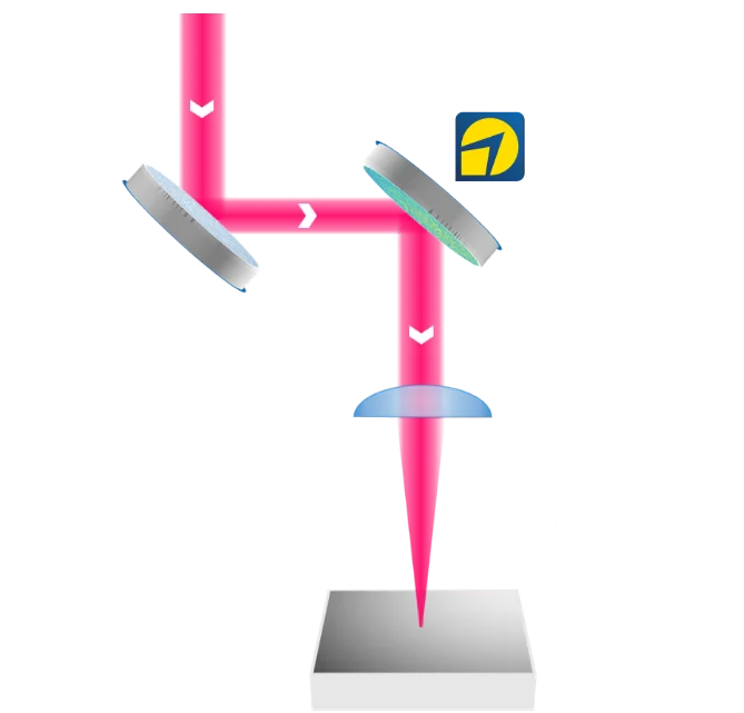
Parallel / Z-folded
Shaper and a folding mirror before the focusing lens: any distance to the lens, focal length f to the part.
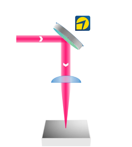
Folded: replaces a mirror
Shaper at 45° folds the beam straight into the lens: takes the place of a deflection mirror already there, no extra space or track length.
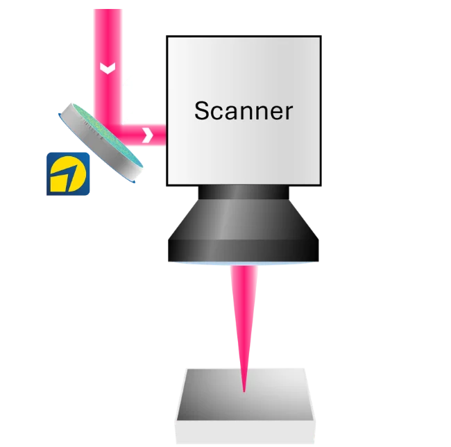
Scanner
Shaper ahead of the scanner and F-Theta lens: ring-core shaping for scanned processing.
Other configurations and angles-of-incidence (AOI) available. Tell us your beam path and we’ll propose the cleanest integration.
Related use cases
Robust high-power laser cutting
Consistent cut quality under thermal drift at 10–50 kW+. Free white paper.
Read use case →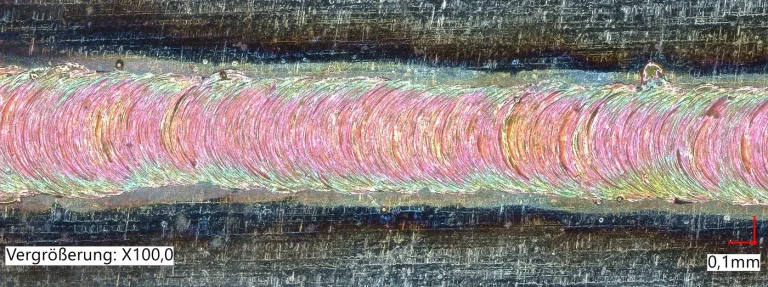
Copper welding, spatter-free
A single-mirror retrofit brought ring-core seams to an existing welding laser.
Read use case →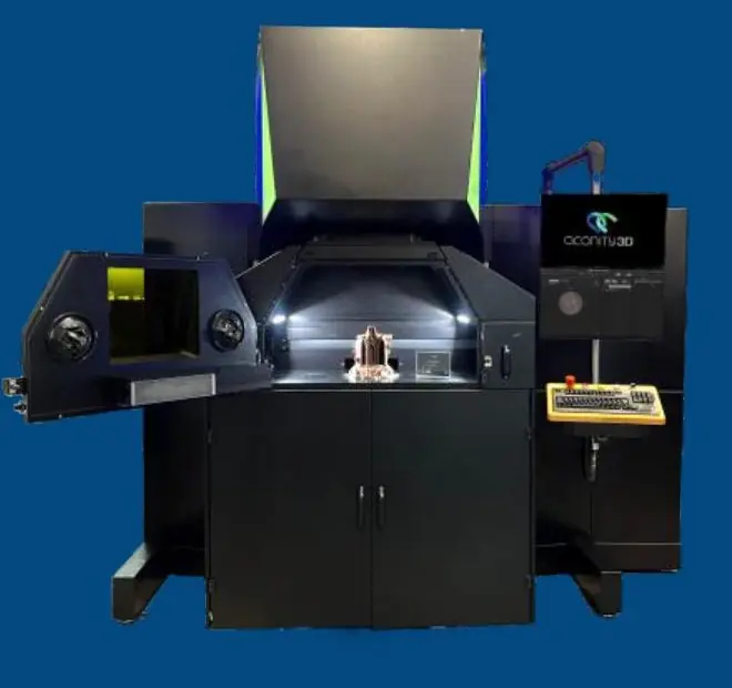
Additive manufacturing (LPBF)
Faster build-up with exchangeable beam shaping in the scanner path.
Read use case →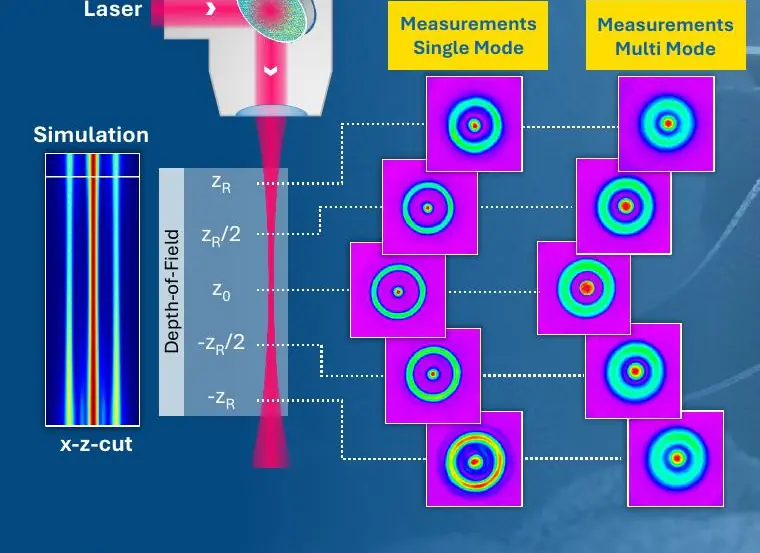
Measured, not just modelled
Independent high-power characterisation of the 3D Ring-Core with PRIMES.
Read case study →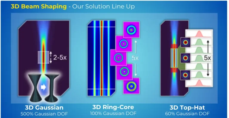
Through-Glass Vias for AI packaging
Why 3D beam shaping is the optics-ready foundation for TGV drilling.
Read white paper →More processes we’ve proven. Some we can’t show publicly.
Explore all use cases →Where it's used
Welding & Cutting
Controlled energy deposition for stable, high-quality joints.
Explore → TGV / HBM, wafer processingSemiconductor & Advanced Packaging
Depth-of-focus and taper control for wafer processing and TGV drilling.
Explore → LPBF spot shapingAdditive Manufacturing
Tailored intensity profiles for productive, repeatable builds.
Explore →Datasheets
Frequently asked questions
Can I set the ring diameter and the ring-to-core power ratio?
Yes, both are customized as standard. Tell us your target ring diameter and how you’d like power split between ring and core, and we design the optic around your process.
Which lasers and power levels does it support?
All of them: deep-UV to near-IR, femtosecond to continuous-wave, and low power up to 50 kW+. It works with single- or multi-mode sources. Send your wavelength, power/regime, M² and input beam and we confirm fit.
Will it survive multi-kW operation?
That’s a core strength. The optic is all-reflective (a micro-structured dielectric HR coating on fused silica with >99.9% reflectivity), so it stays stable where transmissive optics drift under thermal lensing.
How do I integrate it?
We recommend a collimated beam with a focusing lens; the shaper can sit in a parallel/Z-folded, folded, or scanner (F-Theta) path. Lateral alignment is required. For setups without a lens, contact us for analysis.
Can I actually reproduce the measured numbers?
Yes, the values on this page were measured on a Primes MicroSpotMonitor MSM+ and agree with theory. We confirm the numbers for your exact configuration and stay close while you validate them in your process.
What’s the delivery time?
Custom optics are typically delivered within three weeks, depending on configuration.
Is the Ring-Core Shaper right for your process?
Send us your laser and application, and we’ll assess feasibility and start on your ring-core solution together.
Discuss your challenge