



 EN
·
EN
·  DE
DE3D Top-Hat Beam Shapers
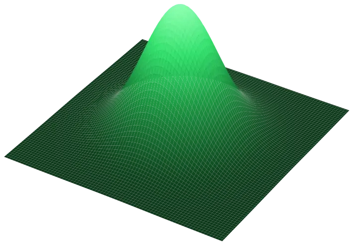
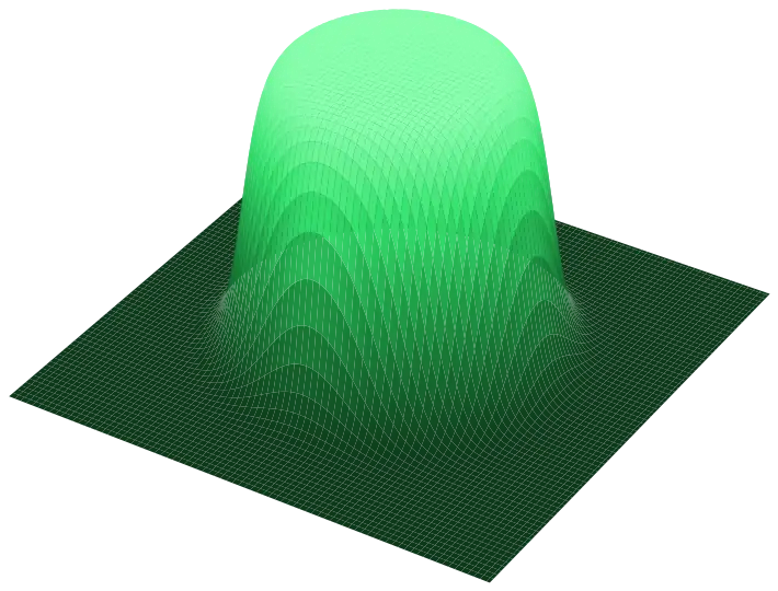
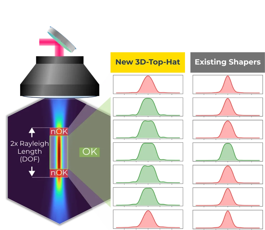
We offer stable top-hats for real industrial production conditions. Shape your Gaussian beam down to the smallest top-hat and quality and speed both jump. Using other top-hat shapers in production, the beam shape usually holds only right at focus. We engineer the depth of field of the beam shape instead, so it stays flat across a much wider working range: up to a 5× larger process window.
A flat-top that survives the move into production
A conventional top-hat only looks good at the focal plane. Move away from it, through defocus, tilt or a change in part height, and the top-hat collapses back toward a gaussian: yield swings, and every job needs an exact refocus. The 3D Top-Hat is engineered for depth of field instead. It holds a clean, homogenized flat-top across an extended usable range around focus, which turns a fragile, focus-critical step into a wide, forgiving process window: faster setup, higher yield, safer processing on the line. And because the fluence stays uniform through depth, the cut itself gets cleaner too, with steeper walls, less taper and better surface quality than a Gaussian.
Built for real production, not just the focal plane
Up to 5× larger process window
Holds a quality flat-top across ±60% of the Rayleigh length under realistic conditions. Regular shapers, by comparison, prove usable only within about ±12.5%.1 The payoff: less focus-shift sensitivity and a far more tolerant configuration.
Smallest possible flat-top
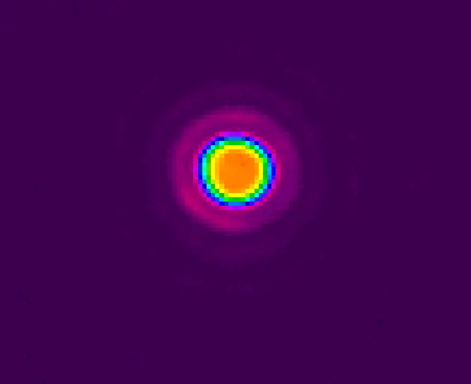
Shapes down to 1.5–1.8× the diffraction-limited spot, close to the physical resolution limit, which gives you uniform energy delivery even at the small feature sizes next-gen micro-machining demands.
High efficiency, clean edges
~85% efficiency with plateau uniformity ≤0.1, flatness ≥0.9 (ISO 13694) and side lobes ≤5%. All-reflective micro-structured mirror optics stay stable at power, without significant thermal-lensing drift.
1 ±60% zR and the ~5× comparison are M²-dependent design/measured figures (regular shapers ~±12.5% zR usable in production practice vs. ±30% specified in theory). Stable range scales with beam quality — see specifications. Confirmed per configuration.
Stability is a depth-of-field problem — so we engineered the depth
Conventional top-hat shapers shape the beam mainly in the focus plane. In production, stability depends on how the beam behaves across the depth of focus. A typical 2D shaper holds a quality top-hat only very close to focus; the 3D Top-Hat keeps it flat over a defined axial range, extending the usable working range under realistic conditions.
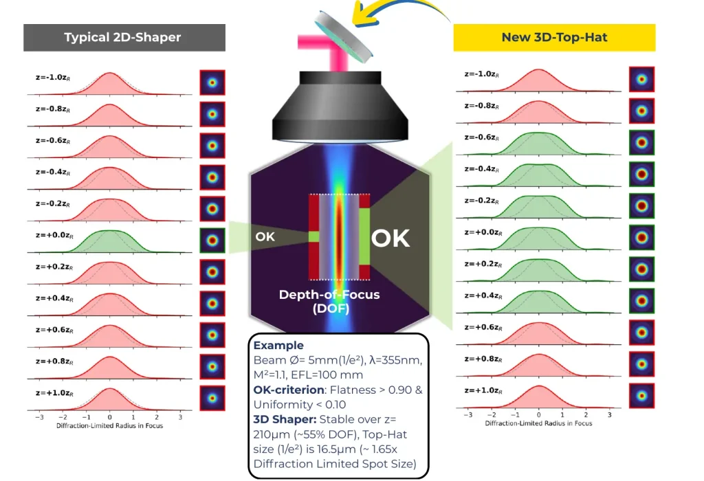
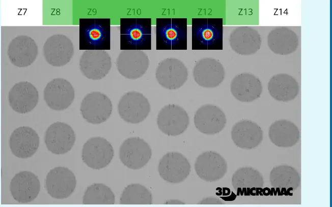
Typical 2D shaper vs. new 3D Top-Hat, profile and 2D spot at each z-plane. Example: Ø 5 mm (1/e²), λ 355 nm, M² 1.1, EFL 100 mm → stable over z ≈ 210 µm (~55% DOF), flat-top ≈ 16.5 µm (~1.65× diffraction-limited spot). OK criterion: flatness >0.90 & uniformity <0.10 (ISO 13694).
Regular shaper
Quality flat-top only within roughly ±12.5% of the Rayleigh length in production practice. Leave that sliver, and it decays back into a gaussian.
3D Top-Hat
Flat-top stays flat, uniform and on-size across ±60% of the Rayleigh length, holding flatness >0.9 and uniformity <0.1 the whole way.
What you get
Wider tolerance to focus shift means faster setup, higher yield and safer processing. And because the top-hat stays uniform through depth, the cut itself improves: steeper walls, less taper and better surface quality than a Gaussian.
Beam-profile stability confirmed by our customers
Measured beam profiles match simulation, staying top-hat across ~60% of the depth of focus. That’s the basis for reliable micro-machining processes.
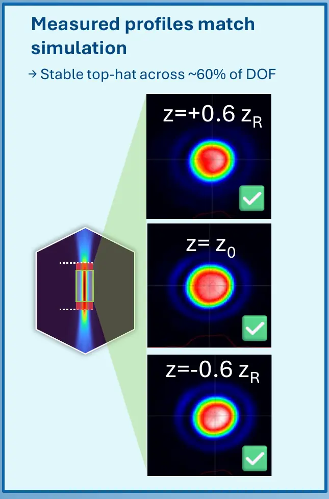
Result: predictable, repeatable ablation with a flatter floor and cleaner walls than a Gaussian — a solid basis for micro-machining. Measured with an industry partner.
Conditions: Values are for the configuration above and depend on wavelength, input beam, M², optical layout and application. We confirm the numbers for your exact setup instead of relying on catalogue guesswork.
Will it fit your setup?
Every 3D Top-Hat is matched to your laser and process. These are the parameters we design against. Send them, and we confirm fit for your exact configuration.
Recommended setup: collimated Gaussian input into a focusing lens. Stable focus range scales with M², so tell us your beam quality and we’ll confirm the usable depth for your process.
What the numbers look like in practice
Take a UV micro-machining setup: a 5 mm input beam at 355 nm, M² 1.1, focused with a 100 mm lens. It yields a flat-top spot of about 16.5 µm (≈1.65× the diffraction limit) that stays stable over roughly ±210 µm of focus travel (~55% of the usable depth) — the difference between a knife-edge focus and a process window you can run.
Illustrative configuration from the datasheet. Exact values are confirmed per setup.
Specifications
| Parameter | Characteristic |
|---|---|
| Output & performance | |
| Output profile | Flat-top (top-hat) — round standard, square on request |
| Shaped diameter | 1.5–1.8 × diffraction-limited spot — M²-dependent (M² 1.0 → 1.8×; 1.1 → 1.7×; 1.2 → 1.6×; 1.3 → 1.5×) |
| Efficiency | ≥ 85% | ≥ 82% (industrial version) |
| Plateau uniformity | ≤ 0.1 (ISO 13694) |
| Flatness | ≥ 0.9 |
| Side lobes | ≤ 5% |
| Stable focus range (z) | ± up to 60% of Rayleigh length — M²-dependent (M² 1.0 → ±1.2 zR; 1.1 → ±1.0 zR; 1.2 → ±0.6 zR; 1.3 → ±0.3 zR) |
| Input beam requirements | |
| Input beam | Gaussian TEM₀₀, M² ≤ 1.3 |
| Regime | CW to 300 fs pulses |
| Input beam diameter | 2.5 / 5.0 / 8.0 mm |
| Wavelengths | 1030–1064 nm; 515–532 nm; 343–355 nm; others on request |
| Clear aperture | ≥ 2× beam diameter |
| Integration | |
| Angle of incidence | 45° |
| Setup | Parallel / Z-folded, folded, or scanner (F-Theta) path |
| Optic | |
| Type | Micro-structured mirror (continuous reflective DOE) |
| Coating | Dielectric HR > 99.9% @ 45° |
| Substrate | Fused silica |
| Dimensions | Ø 25.0 mm × 6.35 mm. Other dimensions on request. |
Exact performance depends on wavelength, input beam, M², optical layout and application, confirmed per configuration.
It mounts like a mirror. It aligns like an optic.
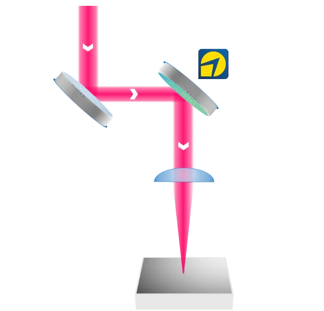
Parallel / Z-folded
Shaper and a folding mirror before the focusing lens — any distance to the lens, focal length f to the part.
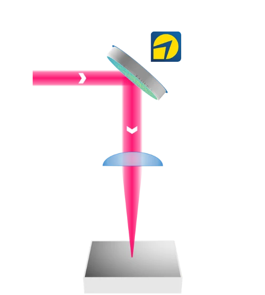
Folded — replaces a mirror
Shaper at 45° folds the beam straight into the lens — takes the place of a deflection mirror already there, no extra space.
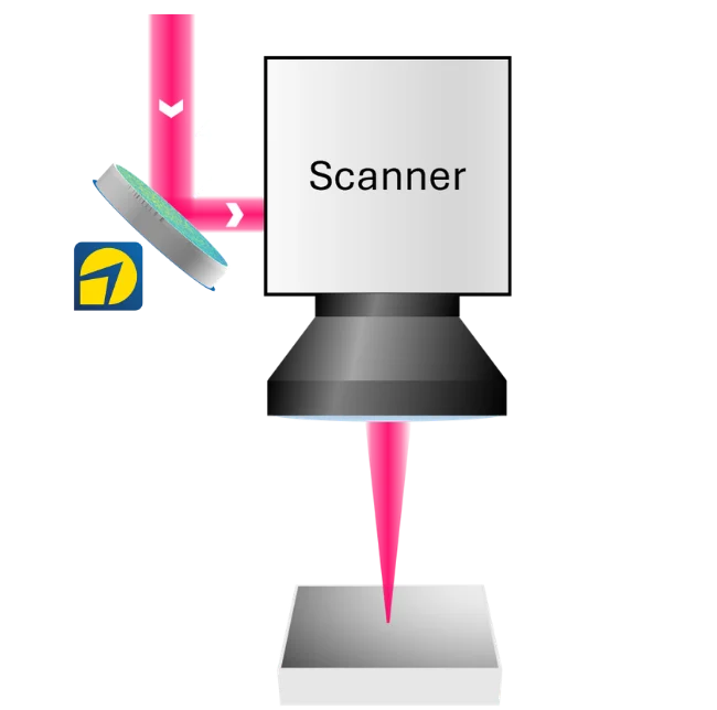
Scanner
Shaper ahead of the scanner and F-Theta lens — flat-top shaping for scanned processing.
Other configurations and angles-of-incidence (AOI) are available. Tell us your beam path and we’ll propose the cleanest integration.
Processes that live or die by the focus window
| Application | What the flat-top delivers | Key industries |
|---|---|---|
| High-quality (black) marking | Deep, uniform contrast; no hot spots → premium quality | Consumer electronics, automotive |
| Laser lift-off (LLO) | Controlled delamination; homogeneous energy delivery | Displays (OLED, µLED, flexible) |
| Precision drilling | No taper; minimal heat-affected zone | PCB, semiconductor packaging, glass |
| Surface microstructuring | Repeatable textures; functionalized surfaces | Medical devices, automotive, PV |
| Fine cutting | Smooth edges; minimal recast / burr | Wafer dicing, medical tech, displays |
Related use cases
Semiconductor processing
A homogenized flat-top that stays on-size across a 4–6 mm focus range.
Read use case → Precision micro-machining
Flatter floors and cleaner walls than a Gaussian, verified against simulation.
Read use case →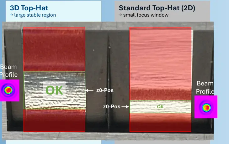
Engraving on a tilted surface
>3× larger process window and >2× better finish across an 8° tilt.
Read use case →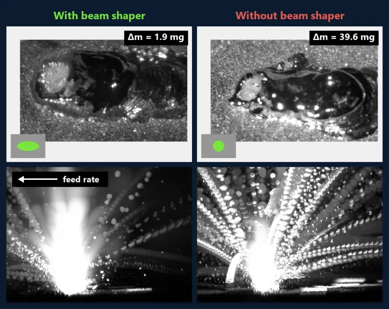
New beam shapes for laser welding
Elliptical flat-top stabilises the copper melt pool — up to 93% less spatter.
Read use case →More processes we’ve proven — some we can’t show publicly.
Explore all use cases →Where it's used
Welding & Cutting
Controlled energy deposition for stable, high-quality joints.
Explore → Fine structuring, high precisionMicromachining & Precision Structuring
Sharper features and a wider, more forgiving process window.
Explore → TGV / HBM, wafer processingSemiconductor & Advanced Packaging
Depth-of-focus and taper control for wafer processing and TGV drilling.
Explore → One optic, no active focusMarking & Traceability
Consistent mark quality on curved or height-varying parts — no f-Theta, no active focus.
Explore →Frequently asked questions
How is this different from a conventional top-hat?
A conventional flat-top DOE only works for a single focal plane and decays into a gaussian as soon as you defocus. The 3D Top-Hat is engineered for depth of field instead: it holds a homogenized flat-top across an extended usable range around focus (up to ±60% of the Rayleigh length), giving you a much wider, more forgiving process window in production.
How much larger is the process window, really?
Up to about 5×. In production practice a regular shaper delivers a quality flat-top only within roughly ±12.5% of the Rayleigh length; the 3D Top-Hat holds flatness >0.9 and uniformity <0.1 across ±60%. The exact figure is M²-dependent — use our interactive calculator to check it for your system.
Which lasers is it compatible with?
A Gaussian TEM₀₀ source with M² ≤ 1.3, from CW to 300 fs pulses, at 1030–1064, 515–532 or 343–355 nm (others on request). Send us your wavelength, regime, M² and input beam diameter and we confirm fit.
How small a flat-top can I get?
Down to about 1.5–1.8× the diffraction-limited spot, depending on beam quality — close to the physical resolution limit, which is what next-gen micro-machining needs.
How do I integrate it?
It’s an all-reflective optic typically at 45° angle of incidence, so in most heads it simply replaces a fold or deflection mirror — no extra track length. It can sit before a focusing lens (parallel/Z-folded), in a folded path, or ahead of a scanner and F-Theta lens. It cleans like a standard mirror.
Can I actually reproduce the specifications?
Yes — that’s the point. Measured profiles match simulation and stay top-hat across ~60% of the depth of focus. We don’t ship catalogue parts with lab-only numbers; we support you through integration and stay close while you validate the profile under your real process conditions.
What’s the delivery time?
Custom optics are typically delivered within three weeks, depending on configuration.
Is the 3D Top-Hat right for your process?
Send us your laser and application. We'll assess feasibility and start your first project together.
Discuss your challenge