




 EN
·
EN
·  DE
DEMultispot Splitter
An all-reflective optic that splits one laser beam into many identical sub-beams: same size, shape and depth of focus, with less than 5% intensity variation across all spots. Parallelize drilling, cutting, scribing or texturing, and put your laser’s full power to work through one passive mirror that survives multi-kW operation.

Process many spots at once: each one identical
A single focused spot leaves most of a high-power laser’s reserve unused. The Multispot Splitter divides the beam into a defined pattern of sub-beams that all keep the original spot’s size, shape and depth of focus, so you drill, cut, scribe or texture many sites in parallel at uniform quality. It’s a single passive, all-reflective optic: it stays stable at power and drops into a collimated beam path without a redesign, and you can stack it with a Top-Hat or other shaper when the sub-beams themselves need shaping.
Built to parallelize production
Faster processing times
Split the beam into many spots and process them simultaneously, putting your laser’s full power reserves to work in parallel.
High uniformity
Typically less than 5% intensity variation across all sub-beams, each with the unaltered size, shape and depth of focus of the input spot. That means consistent results at every site.
Maximum flexibility
Any pattern, 1D or 2D, from a 1×N line to a full grid, and easily combinable with other beam-shaping optics, such as a flat-top shaper or 3D Gaussian on the sub-beams.
Spot pattern, spot count and spacing are individualized to your specification and system as standard. All-reflective, micro-structured mirror optics stay stable at power, which makes them ideal for multi-kW setups where transmissive optics drift.
A 1×4 splitter, measured — four equal spots, no zero order
Sample measurement of one of our splitters on a 532 nm laser: four sub-beams on a 240 µm pitch, each carrying essentially the same energy, with the central zero order suppressed to under 1%.
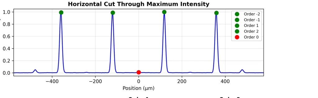
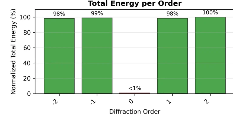
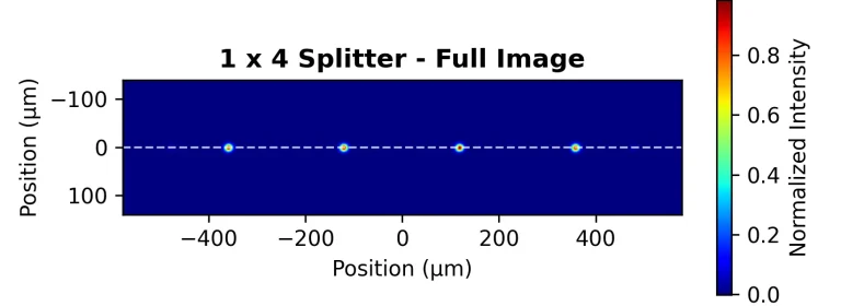
Conditions: sample measurement of a 1×4 splitter on a 532 nm source; values normalized to the brightest spot. Exact spot count, pitch, uniformity and efficiency depend on wavelength, input beam, M², optical layout and application, and we confirm the numbers for your exact setup.
From a line of spots to a full grid
The pattern is a design choice: a 1×N line for scribing and cutting, or a 2D grid for parallel drilling and texturing. We set the spot count and spacing to your process.


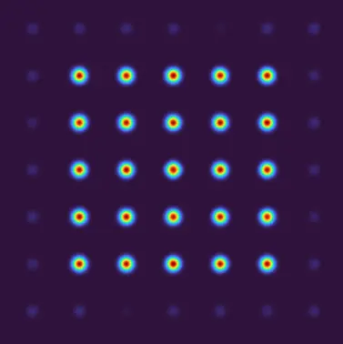
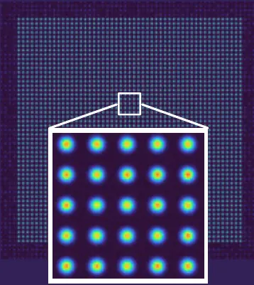
Other patterns, spot counts and spacings are available on request. Tell us your process, and we design the pattern around it.
Specifications
| Parameter | Characteristic |
|---|---|
| Spot geometry | |
| Patterns | Individualized — 1×N lines through 2D grids |
| Sub-spots | Unaltered size, shape and depth-of-focus (DOF) |
| Efficiency | Typically >80–85% | highest-efficiency options on request |
| Homogeneity | <5% intensity variation across sub-beams |
| Maximal outer diameter | Scales with focal length & wavelength — see fit-check |
| Input beam requirements | |
| Input beam | Works with single- or multi-mode |
| Input beam diameter | Up to diameter 16 mm (AOI = 45°) |
| Wavelengths | 1064/1030 nm; 532/515 nm; 450 nm; 355/343 nm; 266 nm; others on request |
| Clear aperture | ≥ 2× beam diameter (1/e²) |
| Integration | |
| Alignment | Insensitive to lateral alignment; rotation not possible (for rotated structures, contact us) |
| Setup | Recommended: integrate into a collimated beam with a focusing lens. For setups without a lens, contact us for analysis. |
| Further specs | |
| Material | Micro-structured dielectric HR coating on fused silica substrate |
| Reflectivity | >99.9% @ 1064/1032 nm; 532/515 nm; 355/343 nm — >99.8% @ 266 nm |
| Dimensions | Ø25 mm/1″ and Ø50 mm/2″. Other dimensions on request. |
Datasheet v1.3. Exact performance depends on wavelength, input beam, M², optical layout and application, confirmed per configuration.
Will it fit your setup?
Every Multispot Splitter is matched to your laser, pattern and process. These are the parameters we design against. Send them, and we confirm fit for your exact configuration.
Recommended setup: integrate into a collimated beam with a focusing lens. Outer spot spacing scales with focal length and wavelength. For setups without a lens, contact us for analysis.
It mounts like a mirror. It aligns like an optic.
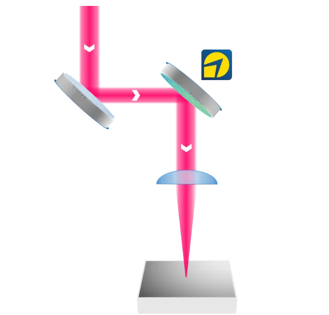
Parallel / Z-folded
Splitter with a folding mirror before the lens — any distance to the lens, focal length f to the part. Optionally add a beam shaper (e.g. flat-top) in the same path.
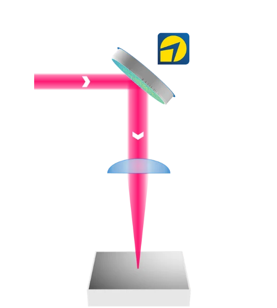
Folded — replaces a mirror
Splitter at 45° folds the beam straight into the lens — drop it in where a deflection mirror already sits, no extra space or track length.
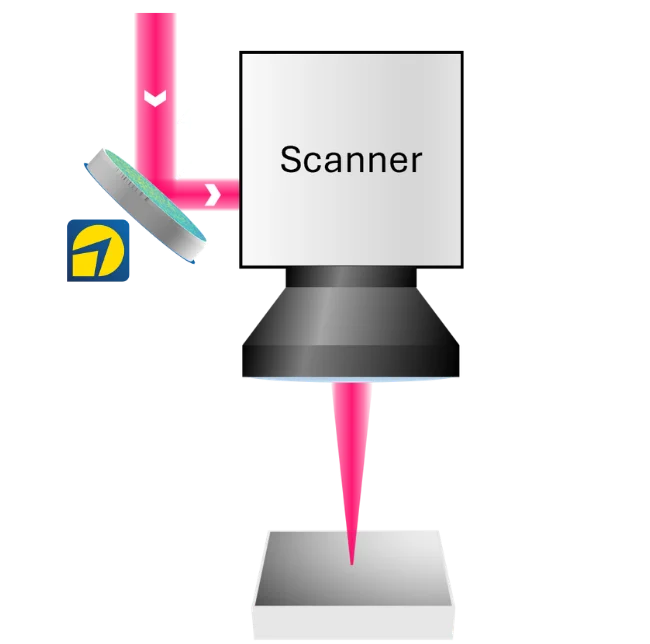
Scanner
Splitter ahead of the scanner and F-Theta lens — multispot processing for scanned applications.
Other configurations and angles-of-incidence (AOI) are available. Tell us your beam path and we’ll propose the cleanest integration.
Where it's used
Micromachining & Precision Structuring
Sharper features and a wider, more forgiving process window.
Explore → TGV / HBM, wafer processingSemiconductor & Advanced Packaging
Depth-of-focus and taper control for wafer processing and TGV drilling.
Explore → Precision beam deliveryLife Sciences & Aesthetics
Homogenized profiles for precise, gentle energy on sensitive materials.
Explore →Datasheets
Frequently asked questions
Can I choose the number of spots and the pattern?
How uniform are the sub-beams?
Can I combine it with a flat-top or other shaper?
Which lasers and power levels does it support?
All of them: deep-UV to near-IR, femtosecond to continuous-wave, and low power up to 50 kW+. It works with single- or multi-mode sources. Send your wavelength, power/regime, M² and input beam and we confirm fit.
Will it survive multi-kW operation?
That’s a core strength. The optic is all-reflective (a micro-structured dielectric HR coating on fused silica with >99.9% reflectivity), so it stays stable where transmissive optics drift under thermal lensing.
How do I integrate it?
Ready to parallelize your process?
Send us your laser, pattern and application. We’ll assess feasibility and work with you to design the right multispot solution, in your hands within three weeks.
Discuss your challenge