


 EN
·
EN
·  DE
DESimple as a mirror, powerful as an optical system
We take a high-quality laser mirror and micro-structure it, shaping the beam on reflection. That reflection already sits in your beam path, so the system gains nothing new: one mirror comes out, one mirror goes in.
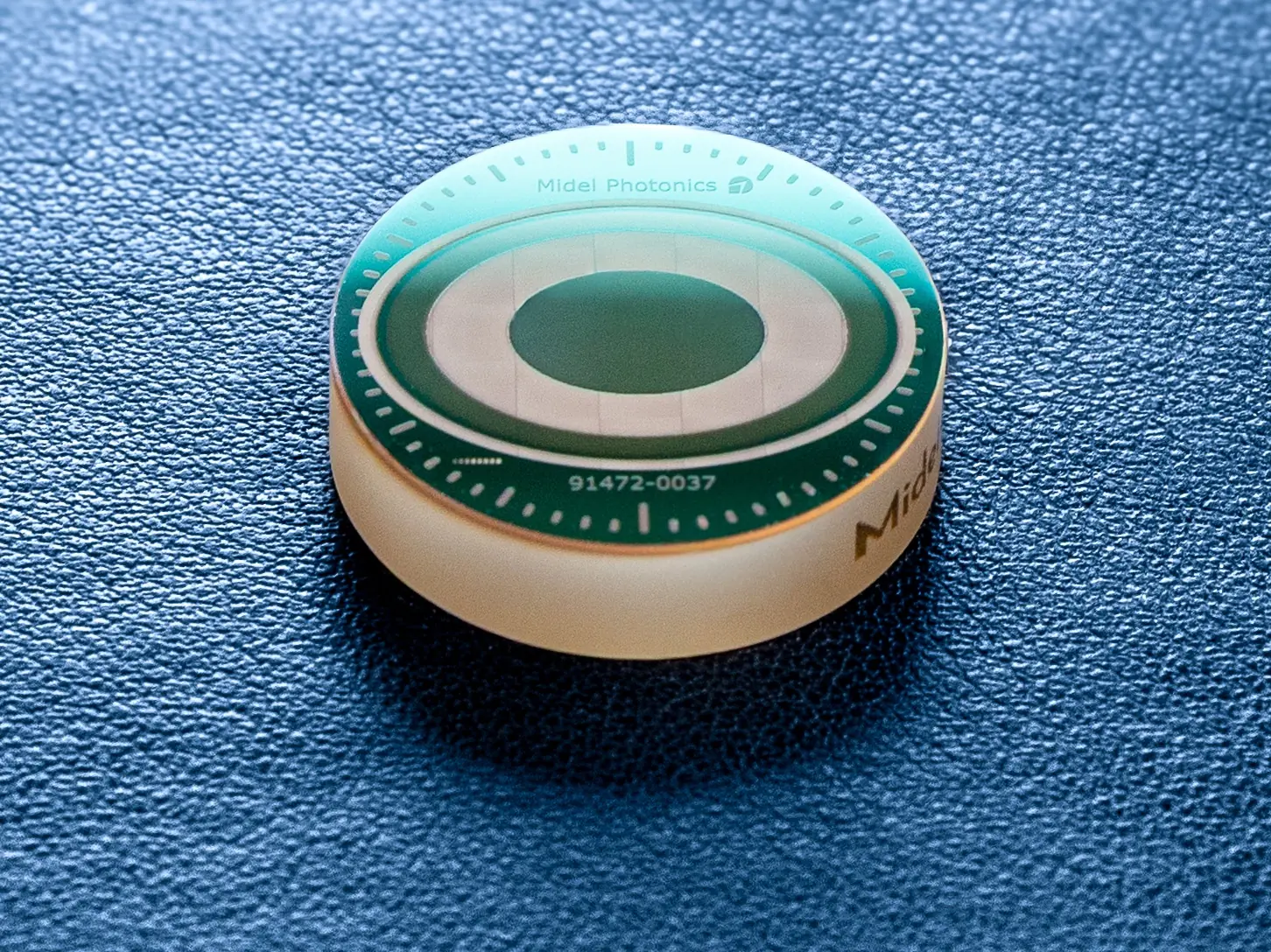
A mirror with a micro-structured surface
It sits in the collimated section of your beam path, ahead of the focusing optic. In most systems, it takes the place of a turning mirror that’s already there.
Micro-structuring lets us modulate the phase of the laser light with high precision. Phase is what makes the difference. An aperture or an amplitude mask shapes a beam by blocking what you don’t want, and you pay for those lost photons. A phase element doesn’t remove light: it redirects it. The structure changes the wavefront, and in the focus of the following lens, the light interferes into the target shape. Nothing is blocked, so most of the energy lands on the workpiece instead of a beam dump. The exact share depends on the design; see “Efficiency into the target profile” below.
It converts the incoming beam into whatever profile the process needs: a flat-top, a ring, a set of spots, or a profile that holds stable through depth. Nothing moves. There’s nothing to power, and nothing to control. And because the shaping happens on reflection, the beam never enters a bulk material: no absorption path, no thermal lens to manage.
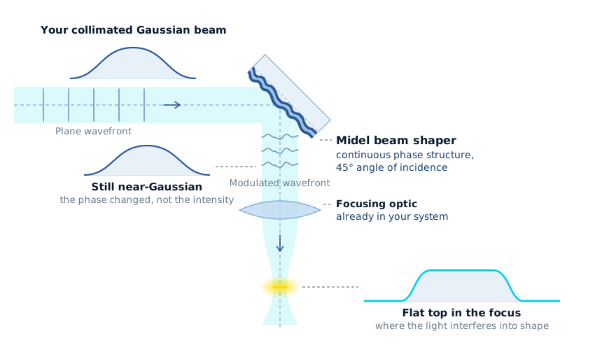
For the optics people: it is a continuous diffractive optical element working in reflection.
Continuous rather than stepped into discrete phase levels, and reflective rather than transmissive. Both follow from how it is made, which is the next section.
Two numbers, kept apart on purpose. The coating returns >99.9 % of the light at the standard NIR, green and UV wavelengths. Efficiency into the target shape is a different figure and we state it per design. What continuous buys you is in the second one: a stepped surface only approximates the target phase, and the approximation error goes into higher orders. With no steps there is no such error.
How we make it
Structured light + high-reflective substrate = reflective beam shaper

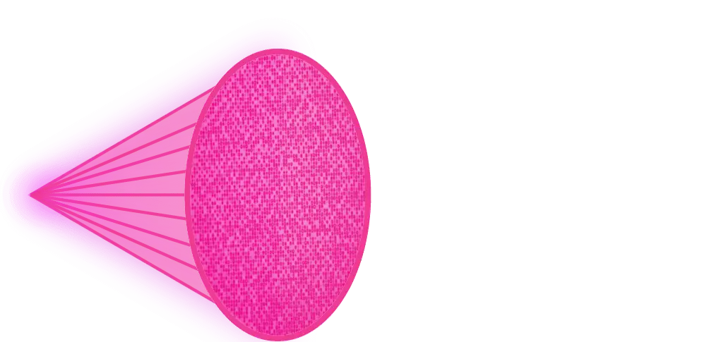
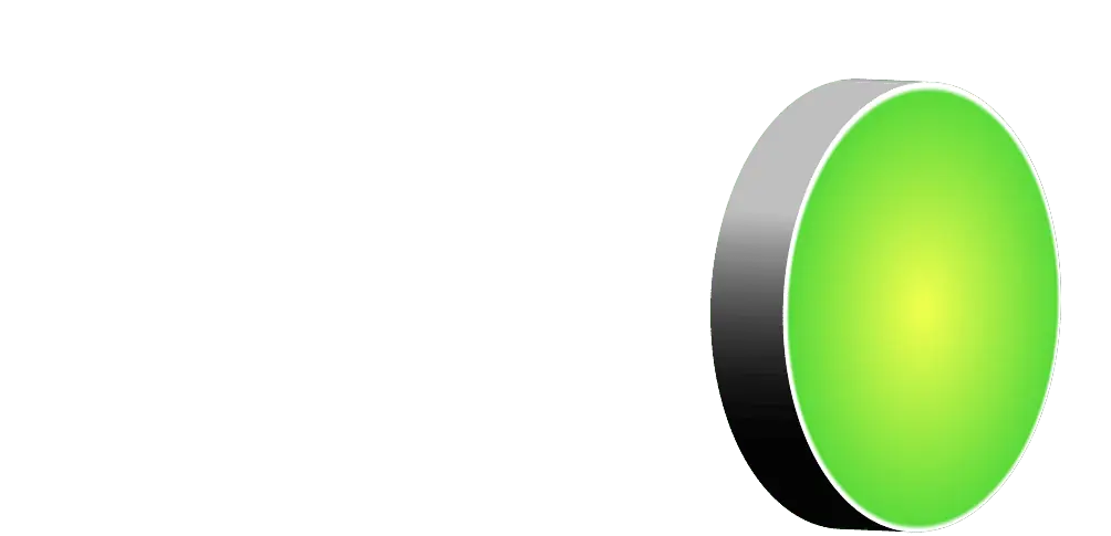


A fully coated laser mirror
Fused silica, dielectric high-reflective coating.
- Coatings made in Europe, from suppliers qualified for high-power laser optics
- High damage thresholds, set by a full dielectric coating and by nothing we add to it
Unique direct laser writing
Micro-delamination writes the structure straight into the mirror. No mask, no lithography, no etching, no added layer.
- No mask and no tooling, so every optic is computed for your target profile and your beam path. Nothing comes out of a catalogue
- A day of production for a single process step, not months of lead time on a mask or a second coating run
- The design is a file: there is no minimum quantity, and the same surface comes back unchanged for the next batch
An all-reflective beam shaper
Modulation depth around half the working wavelength, and transversal features a few micrometres wide. The mirror now carries your custom beam profile.
How do we manufacture an all-reflective beam shaper this fast? Most people assume we take something off the mirror, or put something on it. Either way, the coating stops being a finished mirror coating: etch or ablate it and you lose reflectivity and power handling right where the beam hits. Cover it, and a second material becomes the optical surface. We do neither. We structure the volume between substrate and coating on a nanometre scale and leave the coating exactly as it is. The optical quality you expect from a high-reflective laser mirror stays put.
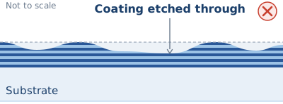

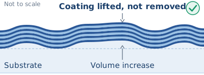
Micro-delamination is our own direct-write approach. The process and the optic it produces are both patented, granted in all major laser markets across Europe, North America and Asia.
Which lasers it works with
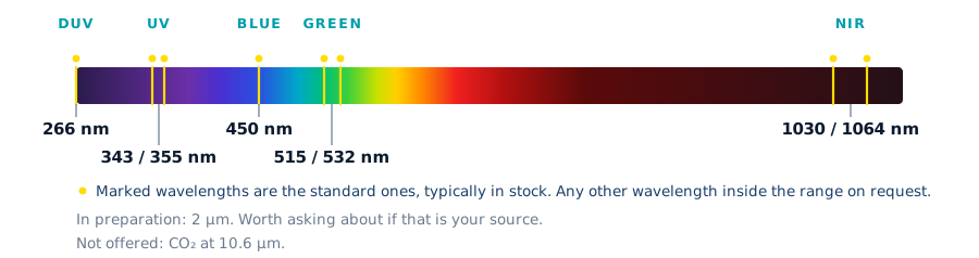
Our beam shapers can be made for a wide range of laser types, currently covering 266 nm to 1100 nm, single mode and multi mode.
| Parameter | Envelope |
|---|---|
| Pulse regime | Continuous wave through ultrashort pulse, down to 200 fs |
| Power | Low power up to the multi-kilowatt regime |
| Beam quality | Up to you. M² = 1.0 through highly multi mode, M² > 50 |
Substrate, coating, format, aperture
What actually arrives, and the envelope it has to fit into: the beam diameter row is usually the one that decides.
| Parameter | Specification |
|---|---|
| Substrate | Fused silica |
| Surface | Micro-structured dielectric high-reflective coating |
| Reflectivity | >99.9 % at 1064/1032, 532/515 and 355/343 nm · >99.8 % at 266 nm |
| Standard formats | Ø25 mm (1″) and Ø50 mm (2″), round. Other diameters and geometries on request. |
| Input beam diameter, Ø25 mm (1") | Up to 9 mm (1/e²) at 45° angle of incidence. Matched to your beam, ±5 %. |
| Input beam diameter, Ø50 mm (2") | Up to 18 mm (1/e²) at 45° angle of incidence. Matched to your beam, ±5 %. Larger beams on request. |
| Clear aperture | ≥ 2× beam diameter (1/e²) is the optimal condition. We can also adapt the design and optimize for a smaller aperture. |
| Angle of incidence | Designed for a nominal AOI, typically 45°. Tolerance ±1°. |
| Efficiency into the target profile | Design-dependent. For flat-top designs >90 % at 1.5× the Gaussian spot and >95 % at 2–10×. Stated per design. |
Damage thresholds
Our optics handle very high powers. The laser-induced damage thresholds below were measured and verified with external partners, each under the conditions stated with it.
| Regime | Threshold and conditions |
|---|---|
|
CW regime IPG YLS6000-U fiber laser |
CW at 1 µm: Up to 30 MW/cm², measured T(30sec)-on-1 to ISO 21254-2 by Lidaris, an independent LIDT testing lab |
|
Ultrashort pulse regime Light Conversion Pharos SP |
180 fs at 343 nm: Up to 235 mJ/cm², measured S(1000)-on-1 to ISO 21254-2 by Lidaris, an independent LIDT testing lab |
|
Short pulse regime Trumpf TruMicro 8340 |
Demonstrated in operation at 400 W UV, 343 nm, 18 ns, 40 mJ, in cooperation with the University of Duisburg-Essen, Group of Prof. Barcikowski. |
What it needs from your system, and what it cannot do
Most are checks, not obstacles; where one is a real go/no-go we say so on the first call. All of them are cheaper to settle now than after the first part is on your bench.
It needs a collimated section
It belongs where the beam runs parallel with a defined diameter, ahead of the focusing optics. No such section, and it’s a design conversation, not a part swap.
Lateral alignment is required
It mounts like a mirror and aligns like an optic. Every element ships with the procedure, and we stay close through your first integration.
One design is one operating point
One wavelength, one input diameter, one target profile, one orientation. Change any of them and it’s a new part, not a setting; two wavelengths in one path means two optics.
The profile is fixed
A passive optic: no actuator, no control loop. If your process has to switch profiles while it runs, this is the wrong technology, and we’ll say so early.
Deflection angles have a ceiling
Direct writing sets how fine the structure gets laterally, and that caps the deflection angle. Where a profile must be far larger than the beam’s natural focus, or spots sit far apart, etched DOEs reach further.
Not all light lands in the shape
Efficiency into the target profile is stated per design. The rest isn’t blocked and isn’t dumped: it stays in the beam, as a low background around the shape.
What to send us for a fit-check
Four things get you a yes or no. Anything else you have is useful, but not needed to start.
- The laser: wavelength, CW or pulsed, average power, and pulse energy and duration if pulsed
- The beam: collimated diameter and how it is defined (1/e², FWHM), plus M² or BPP
- The optical layout: a sketch is enough. What sits between source and workpiece, focal length, working distance, angle of incidence
- The profile you want: shape, size, and over what working plane or depth range it has to hold
Where this technology ships today
3D Top-Hat
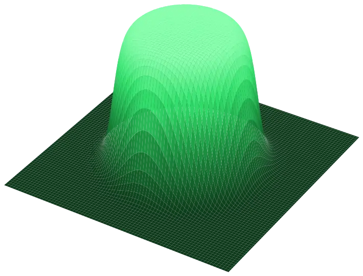
Holds a uniform flat-top across the depth of focus, not just in the focal plane.
Explore → EDOF · focus extension3D Gaussian
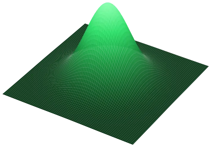
Extends depth of focus up to 5×, so the process stops depending on a knife-edge focus.
Explore → EDOF · ring profile3D Ring-Core
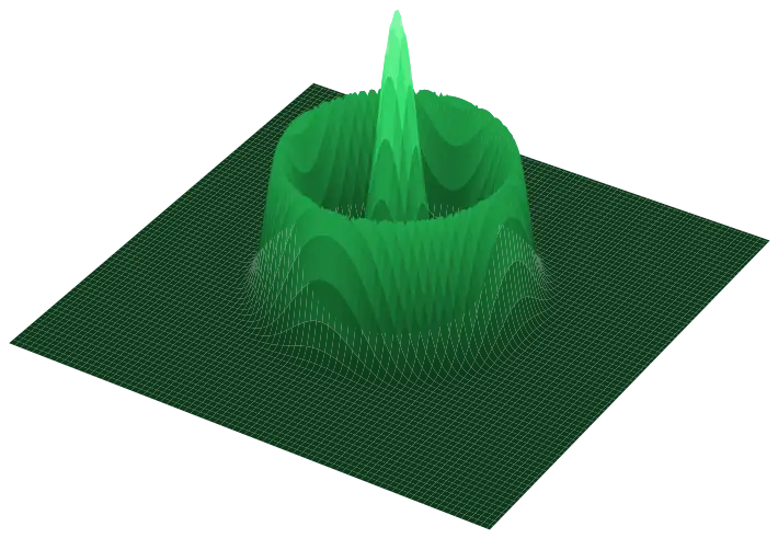
A ring around a core, stable across the full depth of focus: calmer keyhole, less spatter.
Explore →Working on a welding or cutting process today? See Welding & Cutting → for what’s live now.
Frequently asked questions
How is this different from a standard etched DOE?
Will it work with my wavelength and laser type?
How do I integrate it into an existing machine?
Does the structuring lower the damage threshold?
Does this scale to a few hundred units a year?
Ready to see if this fits your process?
Send us your laser and the beam profile you’re after. We’ll assess feasibility and confirm fit for your exact configuration.
Discuss your challengeOutside Germany? We work with you directly there too. In the US, Korea and Japan, our local partners can also support you.