


 EN
·
EN
·  DE
DE3D Gaussian — Interactive Designer Version 1.0 (Beta) EDOF Beam Shaping · Extended Depth of Focus, engineered for your process
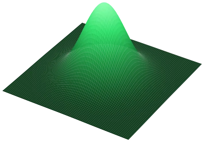
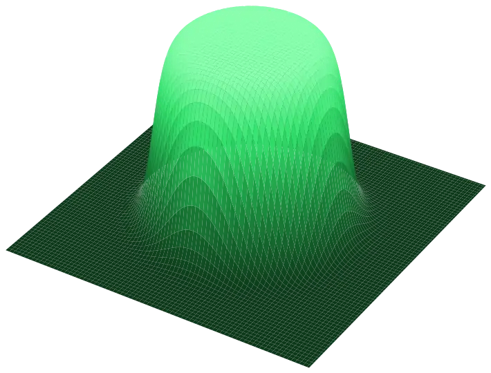
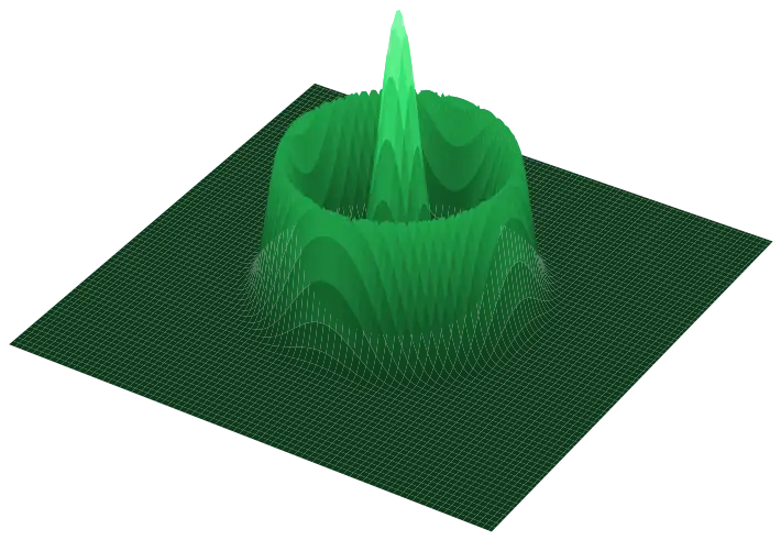
A normal focused Gaussian beam only stays in spec for a short stretch along the axis — move a little off focus and both spot size and intensity drift with it. 3D Gaussian stretches that usable range while keeping a clean, near-Gaussian focus: no Bessel or axicon side lobes, and it works fine with scanners. Put in your system below, then drag the slider and see what the trade-off actually looks like for your numbers.
1 Your system
Keep the smallest clear aperture in your beam path (scanner mirrors, focusing lens, whatever comes last) above 2× the beam diameter at the shaper — go smaller and the numbers below may no longer hold.
Beam Ø over 16 mm is outside our standard aperture (AOI 45°) — talk to us about a custom size.
2 Choose your focus extension
pick whichever one your process actually cares about
3 Your beam, with and without 3D Gaussian
The shaded band shows how long the beam actually stays in spec: the small inner zone is what a plain Gaussian gives you, the wider outer zone is what 3D Gaussian adds. Minimum spot, Usable DOF @10% and Standard DOF @40% come straight from Midel’s measured designs; the curve in between is our best illustration of the shape, and it blends back into the unshaped beam once you’re far from focus — that’s just what a real beam does. Treat the numbers here as a first estimate: your actual design gets simulated and confirmed individually before we quote it.
Usable DOF @10%
–
–
Spot Ø in focus (1/e²)
–
–
Peak intensity / fluence
–
–
Focal spot profile (1/e²)
standard
3D Gaussian
Standard DOF @40%
–
–
Definitions & assumptions
Quantities
Beam quality M² — how close your beam is to a perfect Gaussian
(M² = 1 is perfect). Higher M² means a bigger focus spot and a shorter depth of focus.
Focused spot Ø (1/e²) — the spot you’d get without any shaping, worked out
from your inputs:
d₀ = 4·λ·f·M² / (π·D), where D is your beam diameter at the shaper.Rayleigh length zR —
zR = π·d₀² / (4·λ·M²).
The distance from focus where the beam has grown by √2 in diameter — about 41% wider.Usable DOF @10% — the depth range where the beam stays within 10% of its
smallest diameter:
2·zR·√(1.1²−1) ≈ 0.92·zR. Most processes
use this one; some shops prefer a tighter @5%.Standard DOF @40% — the classic textbook depth of focus,
2·zR, where the beam has grown about 41% by either end.Extension factor ×N — how much longer 3D Gaussian holds your chosen
criterion compared with an unshaped beam. This is what the slider controls.
Spot growth — how much bigger the focused spot gets once shaped. That’s the
trade-off you’re paying for the extended depth of focus, always given relative to your unshaped spot.
Peak intensity / fluence — how much the on-axis peak drops compared with the
unshaped focus. Call it intensity for CW work like welding, fluence for pulsed work
like ablation or drilling — same number either way.
Assumptions & limits
This Beta only covers M² = 1.1 — need a different value, just ask us. The
underlying trade-off data is preliminary and based on designs simulated near M² ≈ 1.
Keep the smallest clear aperture in your beam path above 2× the input beam Ø
at the shaper — smaller than that and these numbers stop being reliable.
The anchor numbers come from Midel’s measured designs; the curve between them is
our best illustration, not a simulation. Every 3D Gaussian we build gets individually simulated
and verified before quotation — treat what you see here as a starting point, not a spec.
Want this checked for your real system? Every 3D Gaussian is simulated and verified for your parameters before we quote it.
Discuss your challenge →